Assembly of JT-60SA related components completed (October 2020)
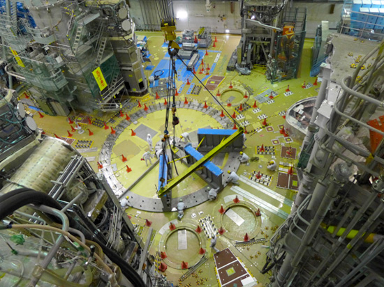
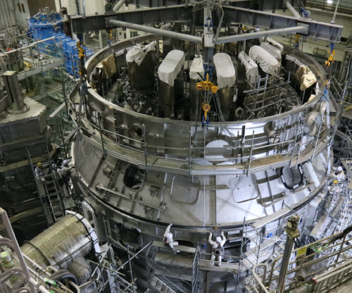
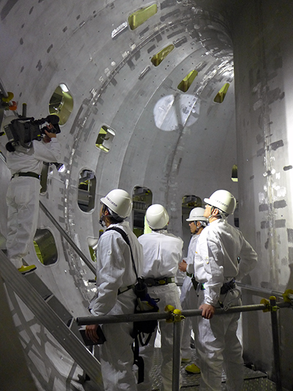
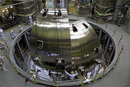
After the assembly of the JT-60SA mainbody was completed, the assembly of some JT-60SA related components such as some components for superconducting equipment and piping has been continued. Then, the assembly of other related components such as common stages, piping for the cryoline, and waveguides for electron cyclotron heating were completed (Fig. 1).
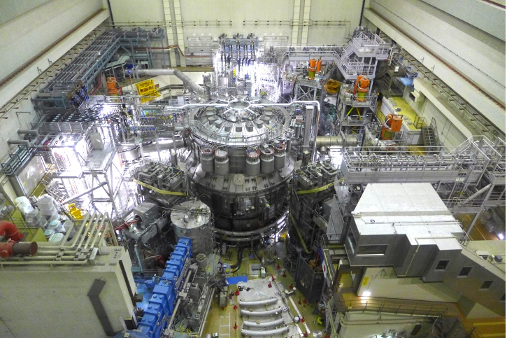
Fig.1 JT-60SA after completion of assembly of related components.
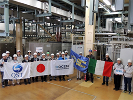
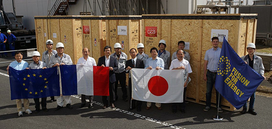
Many research institutes and companies in EU and JA have cooperated in the construction of JT-60SA so far (Fig. 2). Among them, a letter of appreciation was presented by the Managing Director of Fusion Energy Directorate of the National Institutes for Quantum and Radiological Science and Technology to the three companies that made significant contributions to the construction of JT-60SA on schedule.
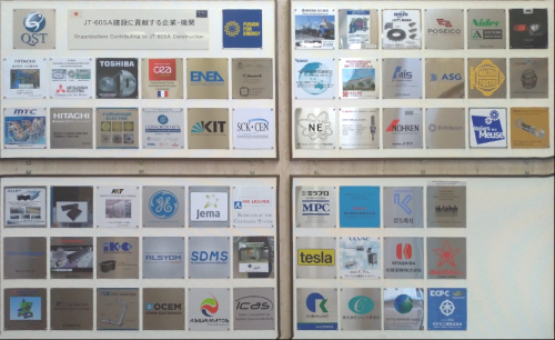
Fig. 2 Examples of companies / organizations that have contributed to the construction of JT-60SA.
It was remarkable that the technology of the high accuracy manufacturing and assembly of large-scaled tokamak devices has been developed. This technology has realized the completion of the manufacturing and assembly of JT-60SA, which leads to the start of the operational phase of the JT-60SA Project. QST presented a certificate to Toshiba Energy Systems & Solutions Corporation and Toshiba Plant Systems & Services Corporation (Fig. 3).
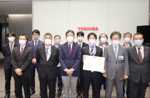
Fig. 3 Presenting a certificate to Toshiba Energy Systems & Solutions Corporation and Toshiba Plant Systems & Services Corporation
The completion of the assembly of first wall and magnetic sensors, that requires a high accuracy of < 1 mm, namely, has been achieved, which has marked a big step toward the operational phase of the JT-60SA Project. QST presented a certificate to Sukegawa Electric CO., LTD (Fig. 4).
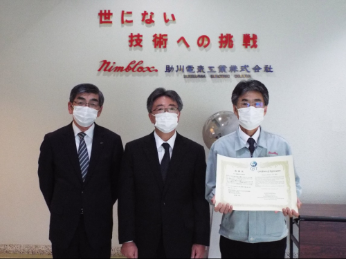
Fig. 4 Presenting a certificate to Sukegawa Electric CO., LTD
The assembly of the superconducting coil feeder, diagnostics, instruments were completed, which has marked a big step toward the operational phase of the JT-60SA Project. QST presented a certificate to JT-60SA team in KURIHALANT (Fig. 5).
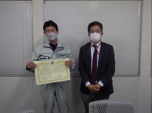
Fig. 5 Presenting a certificate to JT-60SA team in KURIHALANT
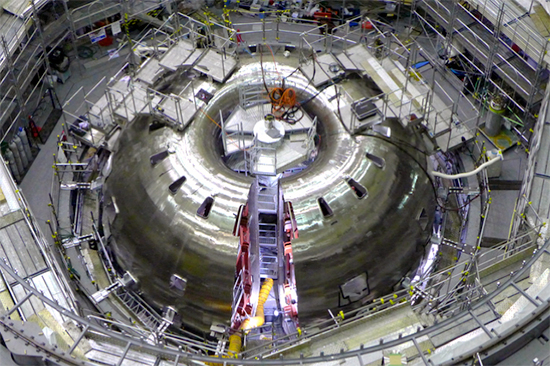
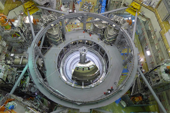
Assembly of JT-60SA tokamak mainbody completed (March 2020)
The JT-60SA program was started in June 2007. The manufacturing of the first equipment (twisted superconducting wires for poloidal coils) was started in October 2008, and the assembly of the cryostat base was started in the torus hall in January 2013. Since then, the manufacturing and assembly of the equipment have been steadily advanced. In the process, several technical problems have been generated, each of which has been solved by the cooperation with Europe. As a result, the assembly of the JT-60 tokamak has been completed.
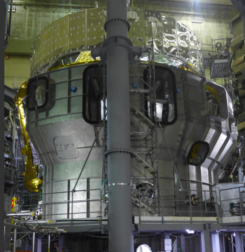
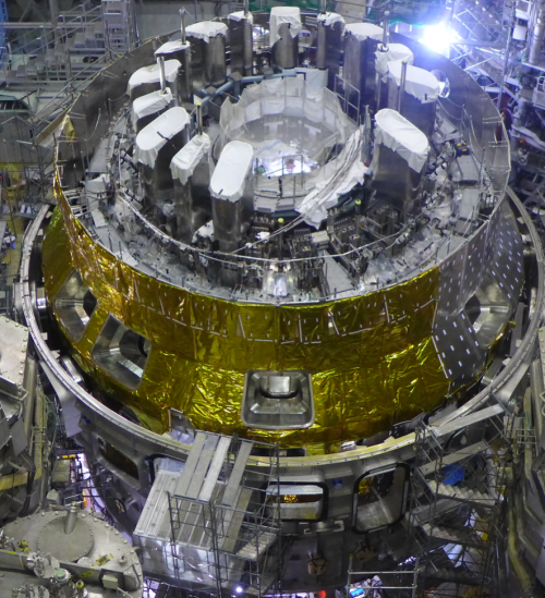
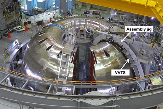
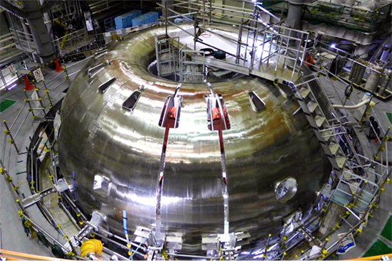
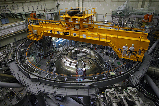
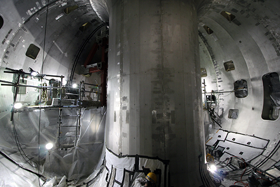
In the final stage of the assembly, the remaining top cryostat thermal shields (TCTSs) which isolate superconducting coils from a high temperature environment (even room temperature is high temperature) around JT-60SA, were installed one after another (Figure 1). The top lid of the cryostat was installed at the end of March 2020 (Figure 2), which completed the assembly of the JT-60SA tokamak mainbody (Figure 3).
The integrated commissioning, where the soundness of each equipment such as pumping out the JT-60SA device and cooling superconducting coils will be confirmed in sequence and the first plasma will be achieved around the autumn of 2020, will start. The operation of the tokamak device in Japan will start for the first time in 12 years since the operation of JT-60 was finished in 2008.
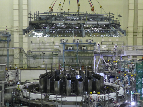
Figure 1 Top cryostat thermal shields being installed
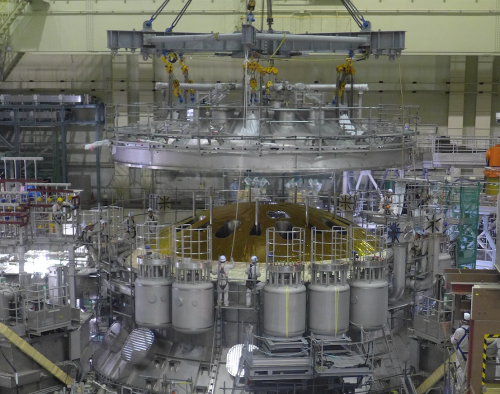
Figure 2 Top lid of cryostat being installed
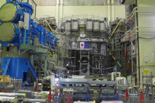
Figure 3 JT-60SA tokamak completed
Cryostat body cylindrical section installed (Dec. 2019)
The JT-60SA superconducting coils must be isolated from warm ambient room temperature to decrease work load of the cryogenic (cooling) system and achieve economical operation. Therefore, the JT-60SA tokamak has the thermal shields and the cryostat which provide vacuum insulation. The JT-60SA cryostat is composed of the cryostat base, cryostat vessel body cylindrical section (CVBCS), and cryostat top lid. The installation of the CVBCS started in September and finished in December.
Starting to install CVBCS (Sep. 2019)
Progressing CVBCS installation (Oct. 2019)
Top part of CVBCS being installed (Dec. 2019)
Installation of top part of CVBCS nears completion (Dec. 2019)
Started to install valve box (VB) and coil terminal box (CTB) (Nov. 2019)
The huge refrigerator having an equivalent cooling power of 9 kW at 4.5 K produces the helium for superconducting coils, but the demand cannot be met without a proper flow management. JT-60SA has many valves capable of performing the flow management. Valve boxes (VBs) are equipped with these valves.
In the power line in JT-60SA, the interface between power supplies at room temperature and superconducting coils is required. The interface is coil terminal boxes (CTBs).
We have started to install the VBs and CTBs.
Installing VB 11 and CTB 5 (Nov. 2019)
Installing VB 11 and CTB 4, 5 (Nov. 2019)
Installing VB10, 11 and CTB4, 5 (Nov. 2019)
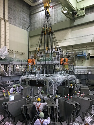
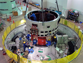
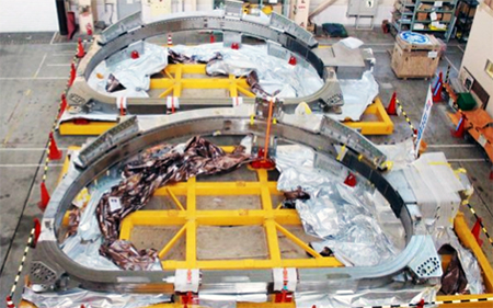
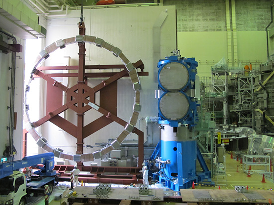
Central solenoid (CS) installed (May 2019)
One of the poloidal field coils in a tokamak is vertically installed in “a doughnut hole” near the centre of the torus, and it is called the central solenoid (CS) (Figure 1). The role of the CS is to produce the plasma current and the poloidal field in the tokamak. The toroidal field coils (TFCs) in the tokamak produce a magnetic field only in the toroidal direction. Therefore, the twisting of the magnetic field needs to be created to avoid “the phenomenon of charge separation” which deteriorates plasma confinement. That magnetic field is the poloidal one generated by the plasma current. The plasma current is generated by induction field which is generated by the CS according to the same principle as a transformer. The plasma current also contributes to heating, and plasma heating by the CS is called ohmic heating (OH). Thus, the CS bears significant meaning for tokamak plasma.
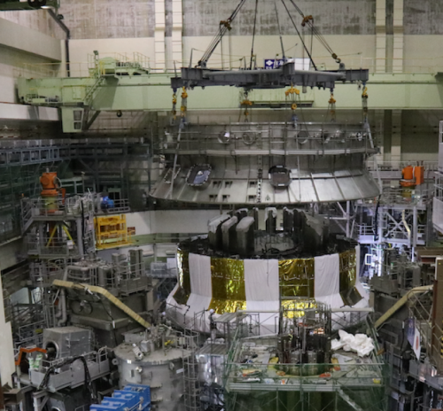
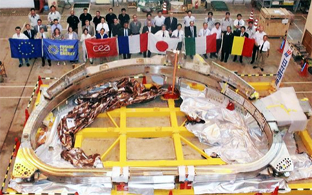
JT-60SA is a low-aspect ratio device to strike a balance between a compact device and large volume plasma. As a result, the space corresponding to “a doughnut hole” is very small, and we need to generate a very strong magnetic field in this small space. Therefore, we decided to adopt niobium-tin (Nb3Sn) super conductor material which is a rather advanced superconductive material in the field of nuclear fusion is used. The CS of JT-60SA is one of the world’s largest coils next to the one of ITER. It is 2 m in diameter, 6.4 m high and weighs 100 t. By energizing Nb3Sn superconductor at 20 kA, an 8.9 T magnetic field is generated. This CS with four modules has been manufactured (Figure 2).
Then it was transported from the factory, and was rotated back vertically in the assembly hall next to the JT-60SA torus hall (Figure 3). It was lifted (Figure 4), and was installed in a given position at the centre of the tokamak (Figure 5).
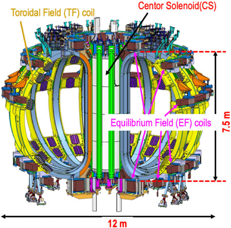
Figure 1. JT-60SA superconducting coils
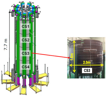
Figure 2. Overall image of CS coil with four modules
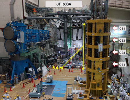
Figure 3. CS rotated back vertically in the assembly hall
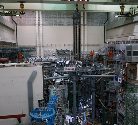
Figure 4. CS being lifted by transport jig
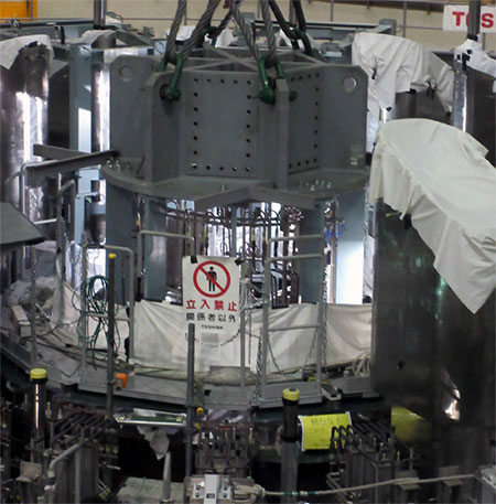
Figure 5. Installation of CS just completed
Installation of horizontal port, oblique port and top lid thermal shields (December 2018)
Here, we will explain about a valve box (VB). JT-60SA uses cryogenic helium for multiple purposes.
It is necessary to reduce heat penetration into the superconducting coils from the surrounding areas to keep the cryogenic state during operation. Heat shield plates called thermal shields are installed in JT-60SA to suppress heat penetration into the superconducting coils. Figure 1 shows the overview of the thermal shields for JT-60SA. The vacuum vessel thermal shields were installed before the installation of the superconducting coils. At present, the remaining thermal shields are being installed from the part where the installation of the superconducting coils has been completed (Figures 2, 3 and 4). The thermal shields are installed in the very narrow space between the devices, but it is necessary to ensure the space which can respond to the displacement associated to the operation and that caused by earthquakes, which requires highly accurate installation. Figure 4 shows the ingenuity to position oblique port thermal shields (OPTSs). The OPTS mounting positions, with respect to the assembly centre, were carefully decided by measuring reference points on the OPTS with a laser tracker. The accurate positioning (± 10 mm) of these mounting points was achieved by using specific couplers aligned onsite. All OPTSs and horizontal port thermal shields have now been installed.
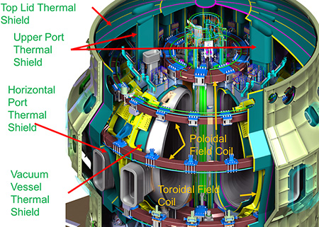
Figure 1. Overview of thermal shields for JT-60SA
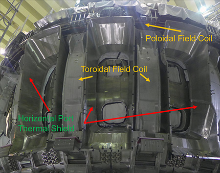
Figure 2. Horizontal port thermal shields
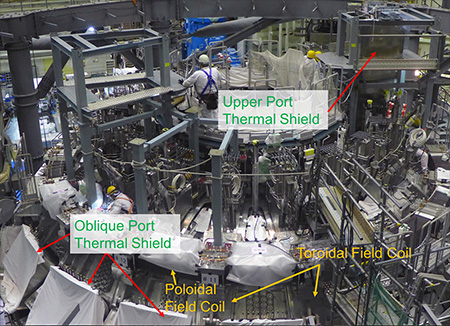
Figure 3. Upper Port and oblique port thermal shields
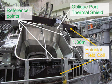
Figure 4. Positioning of oblique port thermal shields
Laser welding tool for divertor cassettes
We will explain about a laser welding tool developed for cooling pipe connection of divertor cassettes. Taking into account the future remodeling and the remote handling (RH) maintenance, all the 36 divertor cassettes of JT-60SA are removable (Figure 1). The JT-60SA divertor cassette has a total of four pipe connections, two in "a forward pipeline" and two in "a return pipeline" as cooling pipe interfaces (on the right side of Figure 2). The stainless steel pipe with an outer diameter of 59.8 mm and a thickness of 2.8 mm is used in the piping for the divertor cassettes to flow cooling water at a pressure of 2 MPa and the flow rate of 750 L/min for removing the maximum stationary heat load of 15 MW/m2. When changing the divertor cassettes, it is necessary to weld and cut four places per cassette in the narrow space. Taking into consideration this work environment, a dedicated laser welding tool usable by RH has been developed (Figure 3). The welding grooves of pipes (the welded interfaces) need to be aligned in a high accuracy. Because pipe connections are in the narrow space, the mechanism to correct the grooves in the limited space is being developed, too. The axial misalignment of the pipes between the vacuum vessel side and the divertor cassette side is a maximum of about 3 mm, which can be reduced to 0.5 mm with the groove matching mechanism developed. The mechanism has been developed for the remaining misalignment of 0.5 mm, which can correctly measure the axial misalignment amount and the gap between the pipes from inside the pipe with a dedicated measurement tool, and also can respond by the movement of the welding tool depending on the situation of the misalignment. We have another issue: we need to prevent atomised metal scattered by welding from splashing the lenses and mirrors in the tool, and prevent oxidation of welding positions during welding. For this purpose, we installed a gas flow system as shown in Figure. 3.
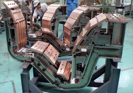
Figure 1. Divertor cassette frames of JT-60SA-armor tiles are not attached
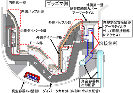
Figure 2. Schematic diagram of divertor cassette of JT-60SA installed-welding and cutting are carried out on the right side
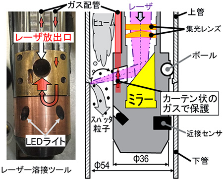
Figure 3. Laser welding tool developed
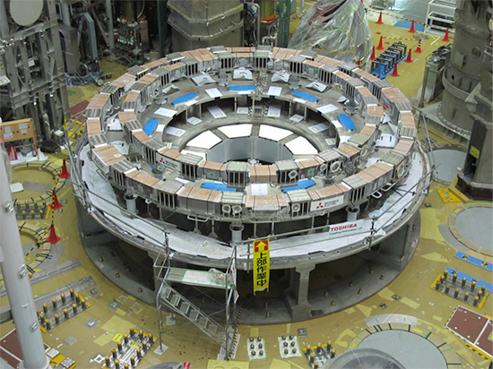
Installation of EF coils 1-3 (August 2018)
After the installation of all toroidal field (TF) coils, the rotary crane used for the installation of the TF coils was removed to make the access from the upper part of the torus easier. Without the rotary crane, the view of all 18 TF coils can be seen from straight above the torus (Figure 1). In this state, the equilibrium field (EF) coils 1-3 at the upper side of the equator were able to be installed (Figure 2). First of all, the EF coil 3 (4.4 m in diameter) was installed (Figure 3), and then the EF coil 1 was installed. The EF coil 1 is 12 m in diameter, which is the world's largest superconducting coil at this time. Figure 4 shows the situation when the EF coil 1 was being brought in. Finally, the EF coil 2 (9.6 m in diameter) was installed, which completed the installation of these three EF coils (Figure 5). The installation tolerance which influences the plasma performance and stability was restricted to within less than 3.5 mm, and the accurate installation was accomplished. From now on, the EF coils 4-6 temporarily mounted on the lower part will be installed in the prescribed positions.
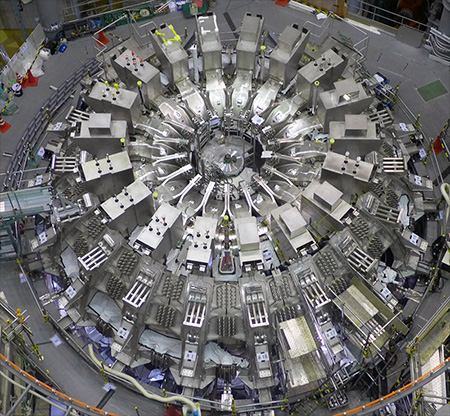
Figure 1. Top view of JT-60SA before installation of EF coils—all 18 TF coils can be seen
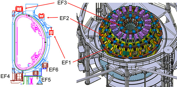
Figure 2. EF coils of JT-60SA
 |
|
| Figure 3. Installing EF coil 3 | Figure 4. Bringing EF coil 1 into the assembly hall |
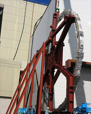
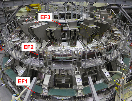
Figure 5. EF coils 1–3 accurately installed
Valve box (August 2018)
Here, we will explain about a valve box (VB). JT-60SA uses cryogenic helium for multiple purposes.
TF coils, equilibrium field (EF) coils and a central solenoid (CS), which are superconducting, are cooled by helium at 4.4 K. The diverter cryopumps are cooled by helium at 3.6 K. The high-temperature ends of high temperature superconductor (HTS) current leads (to connect superconductors and normal conductors) are cooled by relatively high-temperature helium at 50 K. The thermal shields to prevent heat from entering the cryogenic devices are cooled by helium at 80 K. The huge refrigerator having an equivalent cooling power of 9 kW at 4.5 K produces the helium, but the above demand cannot be met without a proper flow management. The JT-60SA has many valves capable of performing the flow management. The VBs are equipped with these valves (Figures 1 and 2). The VBs monitor the state of the helium and adjust its distribution to each device by the elements to measure the temperature, pressure and flow of the helium, as well as the valves, both set inside the VBs. The temperature of the helium is measured by measuring the resistance of the resistive elements set in the piping. The JT-60SA uses the resistive elements formed of different materials such as platinum, carbon and zirconium oxide depending on the temperature range and required precision. The flow is calculated by measuring the pressure difference between the upstream and downstream sides of an orifice plate with a hole in the center, set inside of the piping. The valve used to adjust the flow is a special one having a long valve stem (600-800 mm) between the room temperature region and the cryogenic region to prevent heat from entering the helium from the room temperature region (Figure 3).
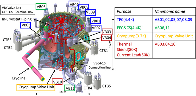
Figure 1. Installed VBs and their uses
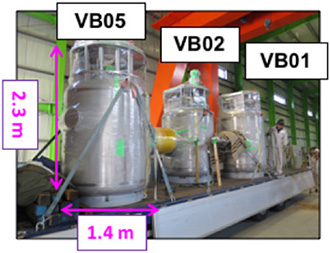
Figure 2. VB01, VB02 and VB05 delivered to Naka Fusion Institute
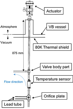
Figure 3. Schematic diagram of cryogenic valve
Torus shape finally appears ! (April 2018)
The completion of the installation of all 18 toroidal field (TF) coils in late April 2018 marked a major milestone.
Figure 1 shows the completion of the installation of the 17 TF coils, just before the installation of the last 18th TF coil. The 18th TF coil and the final sector of the vacuum vessel (VV) and vacuum vessel thermal shields (VVTS) together need to be installed. Therefore, the 18th TF coil and VVTS were assembled onto the final 20°VV sector as shown in Figure 2. This final installation was carried out on 20 April, which was opened to the press and reported by the five news organisations.
Figure 3 shows the completion of the installation. The torus shape finally appeared!
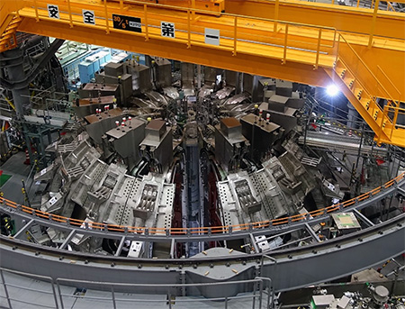
Figure 1. Completion of installation of 17 TF coils
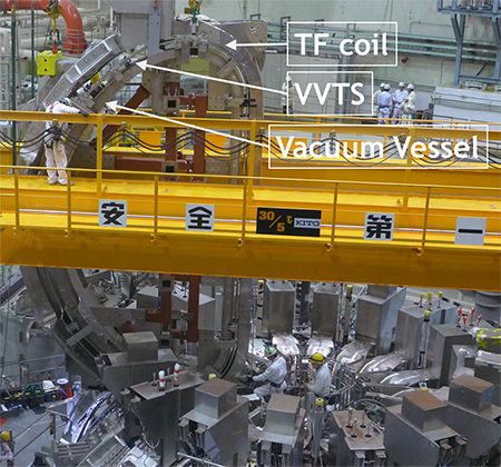
Figure 2. 18th TF coil and VVTS assembled onto final 20°VV sector
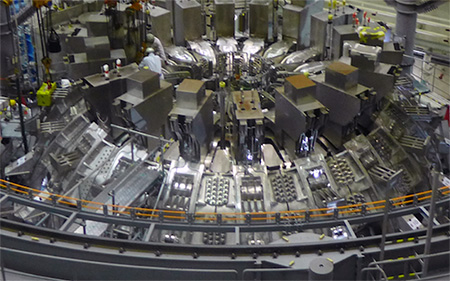
Figure 3. Torus shape finally appears (April 2018).
Transport of two TF coils by airplane (February 2018)
Superconducting toroidal field (TF) coils have been sequentially transported to Japan by ship since 2016, and 14 coils have been installed so far (Figure 1). The cold tests, tests under nominal operational condition (4.5K, 25.7kSA, for the 18th TF coil was completed on 26 January at the CEA Saclay laboratory, France. To promote the assembly, the last two coils were air transported. The TF coil is as large as 7.5 m in height, 4.6 m in width and 20 t in weight. The total size is 9.3 m in height, 5.6 m in width and 34 t in weight when the transport frame is included, and it cannot be loaded on a usual transport airplane. Therefore, one of the word's largest transport planes "ANTONOV An-124" was chartered (Figure 2). Furthermore, considering the huge size and the delivery channel in Japan, Chubu Centrair International Airport was chosen.
The TF coils were loaded on the transport plane An-124 loaded at Châlons Vatry Airport (Figure 3) on 15 February and the airplane took off. On the way, it stopped in Turkmenistan and China for refueling and arrived successfully at Chubu Centrair International Airport in the early morning of 17 February.
The arrival at the airport, the unloading (Figure 4) and the loading of the TF coils (Figure 5) on that day were broadcasted live on the Internet, which has been viewed more than 50,000 times.
Later, the two TF coils arrived at Hitachi Port on 19 February by ship and arrived at the Naka Institute on 21 February. Their installation will be carried out after the adjustment is completed.
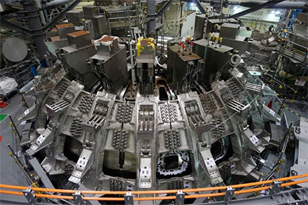
Figure 1. 14 coils have been installed
Figure 2. Large transport plane "ANTONOV An-124" has just arrived at Chubu Centrair International Airport
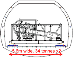
Figure 3. Schematic view loaded on the transport plane An-124
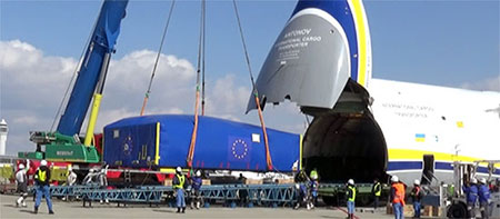
Figure 4. A TFC is being unloaded from the transport plane
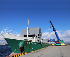
Figure 5. A TFC is being loaded on a transport ship
Installation of current feeder for superconducting coils (February 2018)
In JT60SA, DC current of 25.7 kA is continuously supplied to TF coils, and that of 20kA is supplied to superconducting poloidal field (PF) coils for 220 seconds every 30 minutes. Superconducting wire that generates no heat is used for the coils, while for the connection of superconducting coils and power supplies, conventional aluminum conductors are used from the view point of usability and cost reduction. The cross section of the conductor is rectangular considering heat dissipation, heat generation and the reduction of voltage drop. To handle high current, the cross section of the conductor is very large: that for the TF coil with a cross section of 7cm × 94cm and for the PF coil with that of 7cm × 33cm. For the connection mechanism of the large rigid body handling high current, it is necessary to consider thermal expansions by heat generation. Therefore, for the connection, the flexible conductors formed of multiple layers of welded thin plates were manufactured. These flexible conductors are used to joint a conductor with a DC power supply for toroidal coils (Figure 1) and to joint straight conductors for poloidal coils (Figure 2).
The DC power supply for TF coils is installed in the adjacent building of Tokamak torus building, while that for PF coils is installed in a different building at some distance from it. Hence an inter-building power line was newly installed between the buildings (Figure 3).
The installation which started in August 2014 was completed in February 2018. All the power supply components for TF and PF coils were connected to the torus building, which is about 5300 m in total length and is 330 t in weight. At the Naka Fusion Institute, not only the manufacturing of the power supplies but also that of surrounding facilities has been in progress as scheduled for the first plasma planned in 2020.
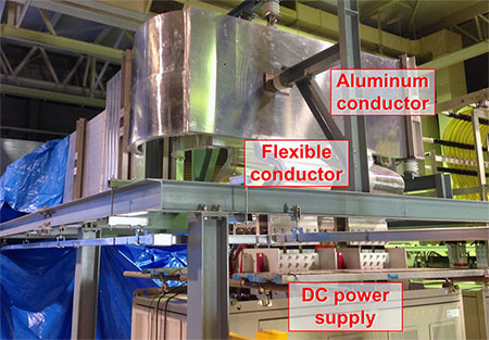
Figure 1. Flexible conductors to joint a conductor with a DC power supply for toroidal coils

Figure 2. Flexible conductors to joint straight conductors for poloidal coils
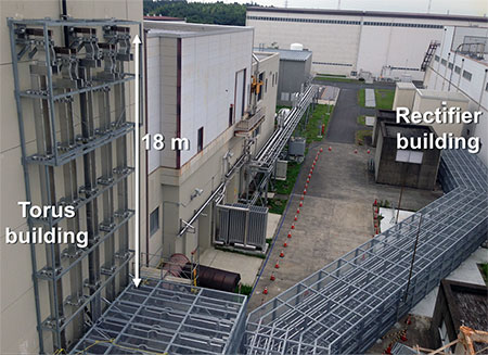
Fig. 3. Newly installed inter-building power line
12th TF coil successfully mounted (September 2017)
Since the toroidal field (TF) coil assembly began in December 2016, a total of 12 TF coils has been mounted around the torus so far (Figure 1).
The TF coils generate the largest magnetic field component among other coils of the JT-60SA tokamak device. Therefore, they must be precisely set in place to minimize error fields, which cause negative effect on plasma performance. So, the coil assembly is carefully performed measuring the coil location with a laser tracker (Figure 2), resulting in a high positional accuracy of ±1 mm (in contrast with the TF coil height of about 7 m).
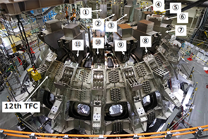
Figure 1: 12 TF coils have been mounted
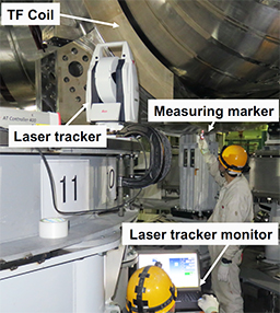
Figure 2: Positioning the TF coil with a laser tracker
Cryostat vessel body cylindrical section in final manufacturing stage (August 2017)
The JT-60SA superconducting coils must be isolated from ambient warm temperature to decrease work load of the cryogenic (cooling) system and achieve economical operation (even room temperature is warm enough for the coils to lose superconductivity). Therefore, the JT-60SA tokamak has the thermal shields and the cryostat which provides vacuum insulation. Especially, the cryostat is such a huge vacuum container as to enclose all of the tokamak components such as the superconducting coil systems, excepting the heating systems installed outside.
The JT-60SA cryostat is composed of the cryostat base, cryostat vessel body cylindrical section (CVBCS), and cryostat top lid. The cryostat base and CVBCS are procured and provided by Europe through CIEMAT in Spain. The cryostat base was installed in the torus hall in March 2013 as the initial JT-60SA component. In August 2017, manufacturing of the CVBCS sectors was almost completed, and its manufacturing accuracy was inspected at the manufacturer窶冱 workshop in Spain.
8 lower and 4 upper sectors were temporarily assembled, respectively. Then, the upper sector ring was lifted and temporarily mounted on the lower sector ring, showing massive whole aspect of the CVBCS with a height of about 11 m and a diameter of about 14m. Subsequently, its dimensions were measured with laser tracker etc. to verify that they were manufactured within the tolerance (e.g. < 5 mm at the large flanges) (Figure 2).
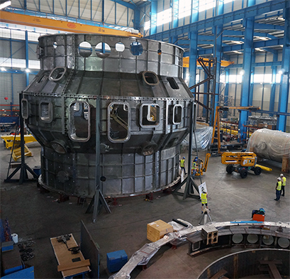
Figure 1: Whole aspect of the CVBCS temporarily assembled
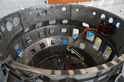
Figure 2: Measuring the CVBSC dimensions
PS installation and commissioning progressing steadily in collaboration with Europe
(March - April 2017)
The installation and commissioning of the superconducting magnet power supplies (SCMPSs) procured by Europe and the maintenance of the existing facilities at the JT-60SA construction site by Japan are progressing steadily.
The existing flywheel motor generator (H-MG) feeds the central solenoid (CS) and equilibrium field coils through the DC PSs (thyristor rectifiers) procured by Europe.
With regard to the European activities, 4 units of the French DC PSs, which were delivered to the site in June 2016, have already been installed and commissioned. Those power tests, which will be performed from May to July 2017, are in preparation now. The work has been jointly performed by engineers of the SCMPS manufacture, Jema Energy S.A., in Spain under the supervision of F4E, CEA (France) and QST. In the upcoming power test, the performance of those DC PSs at the rating operating current of 20 kA will be demonstrated with the existing normal conduction dummy load coils.
As for the Japanese activities, an overhaul of H-MG (Figure left), the inspection and maintenance of the surrounding facilities were completed in March 2017. And then, the rotation test and excitation test were successfully performed. The power receiving test at the DC PSs from H-MG, the preliminary step toward the subsequent electrical current test, are being carried out in collaboration with European staffs.
In the meantime, the procurement of the remaining SCMPS components is underway. The 2 units of the DC PSs for CS1 and CS4 modules, 2 transformers for the CS2 and CS3 modules and fast plasma position control coils, procured by ENEA (Italy), were delivered to the site in March 2017.
In addition, the acceptance tests of the CS switching network units (SNU-CS: the high voltage generators for the CS modules in case of the plasma breakdown and current ramp-up), procured by ENEA, were entirely performed in March 2017 (Figure right). A single SNU-CS will be connected in serial with each of 4 DC PSs. Following the initial excitation of up to 20 kA, the SNU-CS starts. Then, the current flow in the internal resistors induces the counter-electromotive force of maximum 5 kV to the CS (as much as the voltage drops at the resistors). Finally, the loop voltage required for plasma start-up is generated. In the acceptance tests, the performance when 5 kV was induced with the temporary DC PSs and dummy load coils were confirmed by the staffs of the manufacture, OCEM Energy Technology S.r.L. (Italy), F4E and QST.
The electrical current test, connecting European and Japanese components, will be carried out in earnest from now on.
Overhauling H-MG (pulling out the stator)
SNU-CS successfully passed the acceptance tests
Celebration of TF coil fabrication progress in Europe and assembly start in Japan (12 January 2017)
France and Italy procure the superconducting toroidal field coils (TFCs) for JT-60SA from the French and Italian coil manufactures, respectively. The TFC assembly (installation onto the torus) was begun at QST Naka Fusion Institute in December 2016.
In addition, the commissioning of the cryogenic system, which is to cool the JT-60SA superconducting coils and one of the world's largest helium refrigerators for nuclear fusion, was successfully completed. Its ownership has already been transferred to QST from CEA (France) in charge of procurement.
To demonstrate those achievements, a "Celebration of the start of the assembly of TFCs for JT-60SA fabricated by French and Italian Contributors" and a site tour were held at Naka Institute on 12 January 2017. A total of 147 guests from Europe and Japan, including Mr. Toshiei Mizuochi (State Minister of MEXT, Japan) and Mr. Gerassimos Thomas (Deputy Director-General, DG Energy, European Commission) attended to the ceremony. Many guests delivered the congratulatory and encouraging address, and the celebration was performed a great success. This event was covered by the press with interest and reported by 5 news media including NHK.
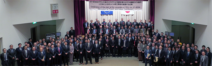
Group photo of the attendees to the celebration
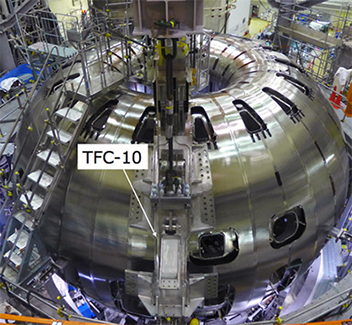
Toroidal field coil assembly starts (December 2016)
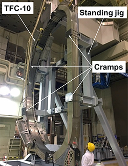
Following the completion of 340° vacuum vessel thermal shield (VVTS) assembly, the assembly of the toroidal field coils began. The TF coils are the most important components for the torus type plasma confinement device.
The first coil (TFC-10) was erected with a dedicated standing jig to measure the deformation by its own weight. Such deformation causes the error magnetic field which deteriorates plasma performance. In the TF coil assembly, the coils will be installed while such deformation is measured with a laser tracker and modified by precise positioning with jacks.
The TFC-10 was successfully inserted from the 20° VVTS opening and finally transported to the appropriate position (opposite to the 20° opening).
Erected TFC-10
TFC-10 installed to the appropriate position
(opposite to the opening)
340° vacuum vessel thermal shield completed (September 2016)
The JT-60SA superconducting coils will be cooled down to cryogenic temperature (4K) during the operations. In order to maintain such a cryogenic state, it is necessary to reduce the heat intrusion from the surrounding components.
The JT-60SA has the thermal shields (TSs), consists of double stainless panels, with a thickness of 3 mm, with cooling pipes located in between. In the JT-60SA operation, 80 K gaseous Helium is circulated through the pipes to cool the TSs and supress the heat intrusion to the superconducting coils.
The vacuum vessel thermal shields (VVTSs) mainly shield the radiation from the VV (at room temperature in operation). The VVTS assembly, which began in January 2015, finished this month except the final 20°sector. The final sector is necessary to be unmounted for the later toroidal field coil assembly. The final sector was temporarily inserted into the 20° opening and its connection with the both 340° sector ends was checked as well.
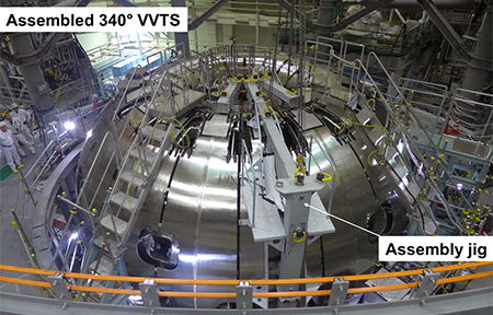
Assembled VVTSs
EF coils completed (August 2016)
In the JT-60SA project, Europe manufactures 18 superconducting toroidal field (TF) coils, and Japan produces 6 superconducting equilibrium field (EF) coils and 1 superconducting central solenoid. 3 EF coils to be positioned at the lower side of tokamak (EF4, EF5 and EF6) have already been completed and temporarily installed to the bottom of the 340° vacuum vessel (VV) in the JT-60 torus hall. This month, the remaining 3 EF coils to be mounted to the upper side (EF1, EF2 and EF3) were completed.
The EF1 (an outer diameter of 12.0 m and a weight of 27 t), EF2 (an outer diameter of 9.6 m and a weight of 27 t), and EF3 (an outer diameter of 4.4 m and a weight of 21 t) had been manufactured in the superconducting coil winding building of the Naka institute since July 2014. Especially, the EF1 is the largest among all of the JT-60SA coils. Those large superconducting coils were produced with excellent high precision of ±0.2 mm. The coils are scheduled to be transported to the JT-60 assembly hall and mounted to the tokamak, after the TF coil assembly is finished and the final 20° VV sector is inserted and jointed.
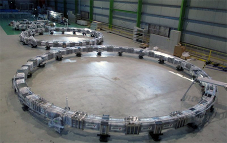
3 upper EF coils completed and waiting for the later assembly
TF coil delivery to Naka institute begins (July 2016)
The JT-60SA construction is progressing steadily at Naka Fusion Institute. The delivery of the superconducting toroidal field (TF) coils, procured by Europe, to the Naka institute started this month.
JT-60SA has a total of 18 TF coils, whose conductors are made from Niobium Titanium (NbTi) that enables continuous energization. Those coils are manufactured by Europe (9 each by France and Italy) and mounted to the tokamak by Japan. This month, the initial and second delivery of the coils, manufactured by France, arrived at the port of Hitachi in Japan via marine transport. And then, they were delivered to the Naka institute on July 20 and August 25, 2016. European colleagues has decided to give a female name to each coil at the shipment from Europe. The first and second coils were named ANNIE and BRIGITTE, respectively.
On July 26 2016 (soon after the initial TF coil delivery), "Celebration of Steady Progress of Delivery, Installation and Commissioning of JT-60SA Component Procured by France" was held at the Naka institute. The participants from France and Japan celebrated the start of the TF coil delivery.
First and second TF coils delivered to the Naka institute (French contribution)
With the first TF coil at the celebration of the French procurement progress
European SCMPSs arrives (June 2016)
The systems and components, which Europe procures for JT-60SA, have been delivered steadily. The superconducting magnet power supplies (SCMPSs) procured by France were delivered to the Naka Fusion Institute at the end of June 2016.
The PSs delivered this time were a total of 5 thyristor DC PSs to be connected to the toroidal field (TF) coils and 4 poloidal field (PF) coils. The TF coil PS continuously supplies a unipolar output of 80V/25.7A at maximum. The PF coil PSs supply the bipolar output of 1kV/20kA at maximum for 220 seconds every 30 minutes. These PSs will be connected to each superconducting coils via a quench protection circuit. In addition, a switching network unit or the booster PSs, which provide a high voltage at the plasma start-up, will be connected to the PF coils.
Following the SCMPS delivery, various tests toward their installation and final acceptance at the site will be performed from now on.
European SCMPSs arrived at the Naka Fusion Institute
VVTS assembly begins (February 2016)
The 340° vacuum vessel (VV) torus, whose assembly began in May 2014, has been completed, and the assembly of the vacuum vessel thermal shields (VVTSs) has been started. Accordingly, a facility tour was offered to the press at the Naka Fusion Institute on 3 February 2016.
The TSs surround the superconducting coils: 18 toroidal field coils, 6 equilibrium field coils, and 1 central solenoid. The VVTSs, whose assembly has recently begun, will be mounted around the VV.
The superconducting coils are cooled down to cryogenic temperature (4K) during the operation. In order to maintain such a cryogenic state, it is required to reduce the heat transfer from the room temperature side. The TS has a double wall, made of 3 mm thick stainless steel. Furthermore, a long cooling pipe to circulate 80K helium throughout the TS is sandwiched between the walls, and cools the TS itself during the operation. Such a structure reduces the heat to the superconducting coils. The VVTSs shield the thermal radiation mainly from the VV, which is at room temperature during the operation.
In addition to the VVTS assembly, the press had a look inside of the VV after the constraint jigs were removed. They seemed to be interested and took many photos of the spacious VV interior.
This facility tour was reported on 6 media afterward.
VVTSs under assembly
Press reporters taking photos of the VV interior
Final VV sector inserted temporarily (December 2015)
The assembly of the 340° vacuum vessel (VV) torus began in May 2014 and finished in August 2015. The final 20° VV sector has not been integrated yet, because the vacuum vessel thermal shields (VVTSs) and toroidal field (TF) coils will be inserted through the 20° gap to be mounted around the VV.
In December 2015, the final 20° sector was temporarily inserted into the gap between the 340° torus ends to measure the complete VV position.
In the JT-60SA tokamak assembly, 17 TF coils, out of 18 in total, will be mounted around the 340ツー VV at first. Then, the 18th VVTS and TF coil will be assembled onto the final 20° sector. Finally, such an integrated sector will be incorporated with the 340° torus. The final sector will be jointed to the torus by welding with the splice plates which are 70 - 110 mm wide. Their shapes will be customised according to the measurements obtained this time.
Although the final sector had not been integrated permanently, the entire 360° VV torus appeared for a moment. It was a rare and valuable opportunity to see the 360° VV torus only, as it will be hidden by the TF coils as the assembly goes on.
360°VV torus after the final 20° sector temporarily inserted
Rotary crane for tokamak assembly installed and constraint jigs for VV removed (October 2015)
The assembly of the 340° vacuum vessel (VV) torus began in May 2014 and finished in August 2015. In October 2015, a rotary crane was mounted on the support structure surrounding the torus. The crane will be used to assemble the vacuum vessel thermal shields (VVTSs) and toroidal field (TF) coils. The VVTSs and TF coils will be inserted through the 20ツー gap of the torus, where the final 20ツー sector has not been installed yet, and then threaded over the VV into their designated positions.
The rated load of the crane is 30 t. It rotates 360° toroidally and moves along the girders horizontally, while pulling up the cargo. Thanks to it, the VVTSs and TF coils will be assembled efficiently.
After the 340° VV torus was completed, the constraint jigs mounted inside of the VV sectors were removed. The jigs had supported the sectors from the inside, and restrained them from deforming when they were set up or jointed by welding.
The jigs were disassembled, while the amount of the VV deformation was carefully checked. All of the jigs, except ones at both ends of the 340° torus, were removed, and a spacious room appeared inside of the VV. It shows how large the JT-60SA plasma will be.
Rotary crane installed for the tokamak assembly
Inside of the VV after the constraint jigs were removed
HTS current leads for TF coils completely delivered (October 2015)
Because the power supplies at room temperature feed the superconducting coils of the JT-60SA device, the thermal interface between the components in room and cryogenic (4.5 K) temperature is required. In the JT-60SA, the coil current with a maximum value of about 26 kA is supplied through a high temperature superconductor (HTS) current lead, made from Bi-2233/AgAu and cooled down to 50 K.
The HTS current leads are procured by Europe. The Karlsruhe Institute of Technology in Germany is responsible for the development and manufacturing of them.
One pair of the HTS current leads for the toroidal field (TF) coils, out of 3 pairs in total, had been delivered before, and the balance (2 pairs) was transported to the Naka Fusion Institute this time. Therefore, all of the 6 current leads (3 pairs) for the TF coils have arrived already.
Hereafter, these HTS current leads will be provided to the manufacturer of TF coil terminal boxes. Then, 10 pairs (a total of 20 current leads) for the poloidal field coils will be delivered to the Naka Fusion Institute in 2016.
HTS current leads for the TF coils delivered completely
340° VV torus completed (August 2015)
The assembly of the 340° vacuum vessel (VV) torus began in May 2014 and finished in August 2015.
The VV has a double walled structure made of thin (18 mm) and low cobalt stainless steel (316L). It is composed of 10 sectors assembled (or to be assembled) on the cryostat base: seven 40°, two 30° and one 20° sectors. The 340° of the entire VV has been completed so far. (The last 20° sector will be incorporated after the other components, such as the vacuum vessel thermal shields (VVTSs) and toroidal field coils, are inserted from the 20° gap and mounted around the VV.)
Firstly, two 110°(40°× 2, 30°× 1) and one 120°(40°× 3) sectors were integrated by welding directly or with the splice plates.
Then, these 3 sectors were jointed to each other by welding with the splice plates. The splice plates are approximately 70 - 100 mm wide. Each plate was customised to adjust a margin in the gap between the sectors so as to accommodate the gaps exceeded the specified tolerances and the thermal deformation by welding, and to maintain the perfect circularity of the VV in the toroidal direction.
The 340°VV torus was fully integrated now. The VVTSs are planned to be assembled hereafter.
VV with a splice plate before welding
340°VV sector integrated by welding
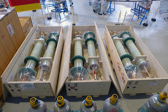
He storage vessels for cryogenic system installed (May 2015)
The JT-60SA device employs the superconducting coils to generate and maintain required magnetic fields for a long time. Accordingly, it also has the cryogenic system, procured by Europe, to cool down the superconducting coils.
The helium (He) refrigerator, which is one of the world's largest, was delivered from France and installed at the Naka site in April 2015. Then, 6 gaseous He storage vessels were delivered and installed in May. A single vessel has a length of 22 m, a diameter of 4 m and a weight of about 70 t.
The vessels were carried by sea from Europe, discharged at Hitachi port in Japan, and one by one transported to the Naka Fusion Institute on the public road while controlling traffics in the midnight hours. At the Naka site, the vessels were lifted and unloaded from a heavy truck and positioned onto the vessel foundations with a 550 t crane. The large-scale and difficult transportation in Japan and installation at the site were completed within about 2 weeks.
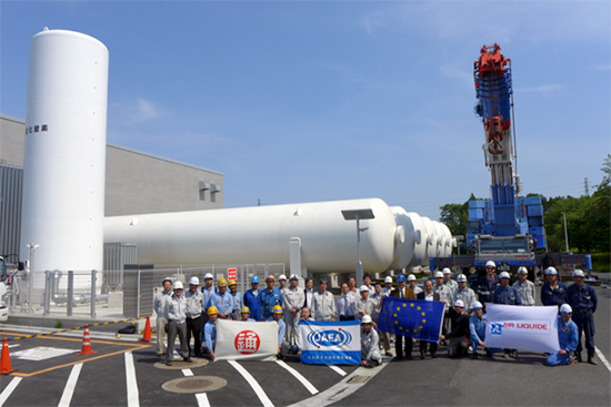
He storage vessels installed and the 550 t crane
Ceremony for the JT-60SA (April 2015)
On 20 April 2015, JAEA held a "Celebration of the delivery of main components and start of their on-site installation by EU, and completion of the initial assembly of the vacuum vessel of the JT-60SA tokamak". More than 200 guests from Europe and Japan, such as Mr. Viorel Isticioaia-Budura (Ambassadors of the European Union to Japan) and Mr. Motoyuki Fujii (State Minister of MEXT, Japan), attended the ceremony and a site tour.
The European contributors, as well as Japanese ones, are responsible for delivery and installation of the JT-60SA components. Recently, the Italian contributor delivered the first lot of the magnet power supply and the French did the main components of the Helium cryogenic system which is one of the world´s largest for nuclear fusion device use. Italian and French engineers have already begun installation on site. The first pair of high temperature superconductor current leads, to provide power for the superconducting coils, also arrived from Germany. This means that the contributors of all European countries concerned have started components delivery, including the Spanish contributors who delivered the cryostat base in January 2013. In the meantime, a Japanese vacuum vessel manufacture finished their initial assembly phase, the 340° structure installation on the cryostat base.
JAEA shared such project status with the guests and received their congratulations and expectations. The ceremony successfully came to a close.
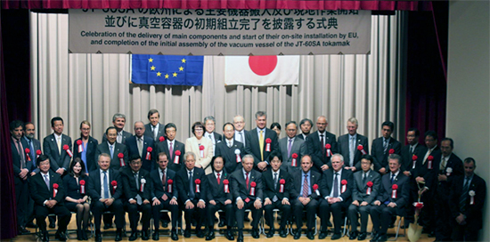
The guests attended the ceremony (at the ceremony hall)
340°VV sector installed (January 2015)
The vacuum vessel (VV) assembly, which started in May 2014, has been progressed steadily in the torus hall. Nine VV sectors forming 340° structure in the toroidal direction were installed on the cryostat base in January 2015. A space on which the last 20° VV sector will be installed is kept empty pending placement of the VV thermal shield, which cuts out thermal radiation between the cryo-cooled superconducting coils and the room-temperature VV wall, and insertion of 18 toloidal field coils procured by Europe. After the completion of the welding between the installed VV sectors, the VV thermal shield insertion work will start in autumn 2015.
Nine VV sectors (340°) installed on the cryostat base
Progress of vacuum vessel assembly and QPC components delivered to Naka (November 2014)
Seventh VV 40° sector installed The vacuum vessel (VV) assembly, which started in May 2014, has been progressed steadily. 10 completely manufactured VV sectors are installed sequentially on the cryostat base to be welded each other. In November 2014, the seventh VV 40° sector was installed and seven VV 40° sectors (280°) were lined up on the cryostat base. The VV sector assembly will be continued until it becomes the 340° structure, and after that, the toroidal field coils (TFCs), manufactured in Europe, will be inserted from the empty space in which the very last VV 20° sector is installed. Finally, the last VV sector together with the last TFC will be installed to complete the 360° structure.
Seven VV 40°sectors (280°) lined up on the cryostat base
QPC components delivered to Naka
In parallel with the VV assembly, the quench protection circuit (QPC) components were delivered from Genoa, Italy to Naka, Japan in September 2014. When a quench occurs in the superconducting coils, the magnetic energy stored in the coils needs to be released while stopping the plasma discharge. The QPC safely converts the magnetic energy stored in the superconducting coils into thermal energy by leading the coil current to damp resistors. The QPC will be connected in series with the toroidal field coils and poloidal field coils in future.
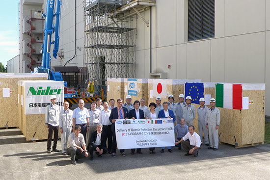
QPC components delivered from Genoa, Italy
JT-60SA vacuum vessel assembly starts (May 2014)
The assembly of the superconducting tokamak JT-60SA has been fully in progress at the Naka Fusion Institute. In May 2014, the assembly of the vacuum vessel (VV), which confines plasma, has started in the JT-60 torus hall.
In JT-60SA, plasma is confined inside the VV, which is kept under ultrahigh vacuum condition. The VV is a doughnut-shaped double-walled structure made of stainless steel (316L) with an outer diameter of 10 m and a thickness of 18 mm, and its cross-section is D-shaped with a transverse diameter of 3.5 m and a longitudinal diameter of 6.5 m. It consists of 10 parts (sectors): one 20° sector, two 30° sectors and seven 40° sectors, which complete the 360°structure. Since the VV is an extremely large device with a total weight of 150 t, each sector is manufactured and assembled one by one at the VV sector assembly building. The assembly work started in April 2011 and was completed in April 2014. These sectors will be joined and installed using the latest welding technology. The two out of ten sectors were installed on the cryostat base and it was opened to the press on 4 June 2014. In future, the remaining eight sectors will be installed sequentially, and after installing and joining the ninth sector (340°), leaving aside the final (tenth) 20° sector, the assembly of the toroidal field coils, procured by Europe will start.
The second VV sector lifting to be installed on the cryostat base
Two VV sectors installed on the cryostat base
Delivery and temporary installation of JT-60SA equilibrium field coils (January 2014)
The assembly work of the superconducting tokamak JT-60SA has been fully in progress at the Naka Fusion Institute. The lower equilibrium field (EF) coils, which control the plasma position and shape, were delivered to the torus hall and temporarily installed on the cryostat base in the middle of January 2014.
JT-60SA has six EF coils in total and three of them are lower EF coils, EF4 (outer diameter: 4.4 m, weight: 30 t), EF5 (outer diameter: 8.2 m, weight: 23 t) and EF6 (outer diameter: 10.5 m, weight: 33 t) completely manufactured by the end of December 2013. The EF5 and EF6 were manufactured in the PF coil manufacturing building constructed at the Naka Fusion Institute due to their huge size. The completed three EF coils were delivered in three days (15, 18 and 22 January 2014) to the torus hall and then temporarily installed on the cryostat base. Since the EF5 and EF6 are the world´s largest class superconducting coils, they were stood upright and transported through the newly constructed delivery entrance on the wall of torus hall using the transport jig and rails. On 22 January 2014, the EF coil delivery and installation were performed as journalists watched, and successfully completed. In FY2014, the vacuum vessel assembly, whose 10 parts (sectors) have already completed, will start.
The world´s largest class superconducting coil, EF6 entering the assembly hall
Three lower EF coils (EF4, EF5 and EF6) temporarily installed on the cryostat base
Celebration of first EU component delivery and start of tokamak assembly (25 March 2013)
At the Naka Fusion Institute, modification of the JT-60U to a full superconducting tokamak, JT-60SA, has been progressed under the Satellite Tokamak Programme jointly implemented by Europe and Japan, and under the National Centralized Tokamak Programme. The cryostat base, the first major component made in Europe, arrived at the Naka Fusion Institute. On 25 March 2013, the "Celebration of the delivery of the first component from EU and start of assembly of the JT-60SA tokamak" was held.
About 100 guests from home and abroad, including Mr. Teru Fukui, Senior Vice-Minister of MEXT, Japan, Mr. Enrique. Asorey, Deputy Head of Mission, Ambassador of Spain to Japan (on behalf of Ms. Carmen Vela, Secretary of State for Research, Development and Innovation of the Spanish Ministry for Economy and Competitiveness), Mr. Shinichi Sakaki, Deputy Governor of Ibaraki prefecture, and Mr. Toru Umino, Mayor of Naka city, attended the ceremony. In the JT-60 torus hall, where the cryostat base is installed, the bolt tightening ceremony was performed by the representatives with the guests and attendees watching it.
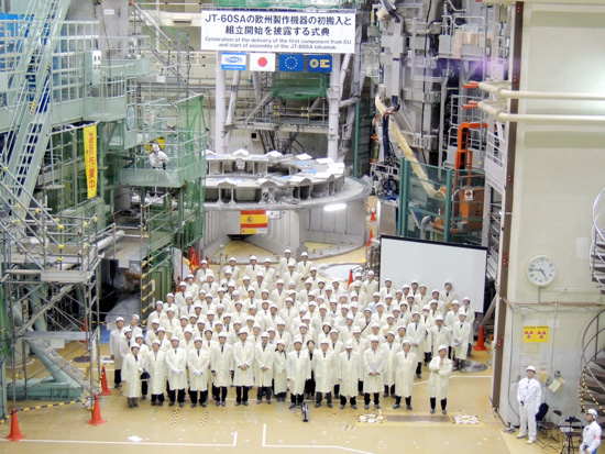
Group photo at bolt tightening ceremony
Start of tokamak assembly (28 January 2013)
At the Naka Fusion Institute, the modification of the JT-60U to a full superconducting tokamak, JT-60SA, has been progressed under the Satellite Tokamak Programme jointly implemented by Europe and Japan, and under the National Centralized Tokamak Programme. The related devices for JT-60SA have been designed and manufactured by Europe and Japan since 2007. The cryostat base, the first major component made in Europe, arrived at the Naka Fusion Institute and the tokamak assembly started.
The cryostat base, a large-scale structure (diameter: 12 m, height: 3 m, weight: 250 t) made of stainless steel, was divided into seven sectors and transported by ship from Spain to Japan. The ground transportation from the port of Hitachi to the Naka Fusion Institute was conducted in seven stages, each time requiring the road to be closed before dawn due to the maximum sector width of 6.5 m. Finally, on 28 January 2013, the tokamak assembly started as many journalists watched. The assembly will take six years to be completed and the operation of JT-60SA will start in 2018.