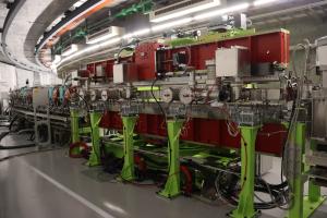
NanoTerasuでは各ビームラインの光源は全て挿入光源を採用しています。研究目的により異なるユーザからの要望に応えるため、ビームライン毎に最適な光源を設置しています。BL02U、BL06U、BL13Uの光源としてはAPPLE-II型アンジュレータを採用しています。アンジュレータは蓄積リング内挿入するように設置されます。強力な磁石により電子ビームを蛇行させることで放射光の強度、エネルギーを制御できます。APPLE-II型アンジュレータはFig.1挿入図のように磁場の相対位置を変えることで偏光をも制御できます。また、アンジュレータの利用によって引き起こされる電子ビーム軌道の乱れは、真空槽面に設置したカレントストリップや挿入光源の前後にステアリング電磁石を設置し、軽減するようにしています。
(参考文献: 放射光学会誌 2024年3月号)
For each beamline in the NanoTerasu accelerator, a light source is installed either in a long straight section (5.44 m) using an undulator or in a short straight section (1.64 m) using a wiggler. APPLE-II type undulators are employed for beamlines BL02U, BL06U, and BL13U, while a wiggler is planned for BL11W (currently under development).
To meet the diverse research needs of beamline users, the magnetic structure parameters have been optimized for each beamline. The key parameters are listed in Table I. Figure 1 shows the peak brilliance produced by the undulators at BL06U and BL02U.
To suppress orbital distortion of the electron beam caused by the operation of the APPLE-II undulator, steering magnets and current strip wires have been implemented. Figure 2 illustrates the configuration of the undulator control system.
We are currently preparing a paper detailing these developments (Hosaka et al.). In addition, we are pursuing high-speed polarization switching using a segmented APPLE-II undulator, and a separate paper describing the current status of this R&D effort is also in preparation (Inaba et al.).
TableI: Key parameters of the undulators
| BL | Light Source TYPE |
Period length (mm) | Number of Periods | Minimum gap (mm) | Maximum gap (mm) | Ky value, Gap=15mm, Phase=0° |
Kx value, Gap=15mm, Phase=0° |
| BL02U | APPLE-II-SX | 56 | 71 | 15 | 220 | 4.7 | 3.3 |
| BL06U | APPLE-II-EUV | 75 | 53 | 15 | 220 | 7.7 | 5.7 |
| BL11W | MPW | 120 | 5 | 15 | 15 | ||
| BL13U | Segmented APPLE-II-SX | 56 | 10×4 | 15 | 220 | 4.7 | 3.3 |
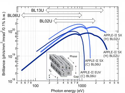
Figure 1: The peak brilliance produced by the undulators at beamlines BL06U and BL02U. The inset illustrates the magnetic configuration of an APPLE-type undulator. H and C indicate horizontal and circular polarization.
Users can change the X-ray polarization by adjusting the phase shift of the magnet arrays. The arrows at the top indicate the energy range covered by the beamline monochromators. Beamline BL13U can utilize the third harmonic of the radiation, enabling measurements at higher photon energies.
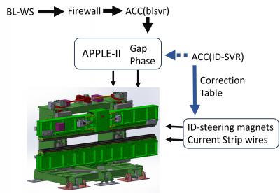
Figure 2: Diagram of the undulator control system.
The operation request for the insertion device (ID) from a beamline workstation (BL-WS) installed at the endstation is sent through a firewall to the accelerator control system (ACC [blsvr]).
The encoder values indicating the gap and phase positions of the ID are monitored by the ID server on the accelerator control system side (ACC [IDSVR]).
Based on these encoder values, a pre-determined current is applied to the steering magnets and current strips to generate the required magnetic field. This monitoring loop operates on a 300-millisecond cycle.
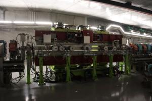
写真集/Photoalbum
BL02U
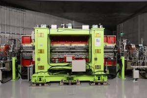
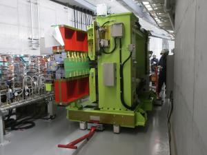
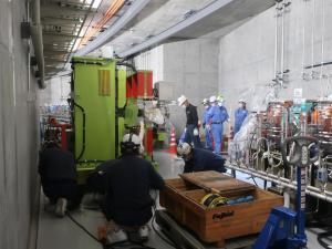
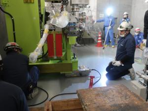
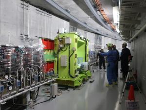
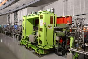
ID06U

ID13U

Current strip wire

2022. Dec. Installing ID06U