II. JFT-2M PROGRAM
JFT-2M carries out advanced and basic research for the development of high-performance plasmas for nuclear fusion, making use of the mobility of a medium-sized device. Both domestic and international cooperations are intensively utilized. In FY 1998, following subjects were mainly pursued. For the core plasma research, the confinement study with a heavy ion beam probe (HIBP) in collaboration with National Institute for Fusion Science (NIFS) and the electron cyclotron current drive experiment were carried out. For the peripheral plasma research, the closed divertor and the compact toroid injection for the development of advanced fuelling were investigated. The latter was done in collaboration with the Himeji Institute of Technology and NIFS. Design and preparation for the Advanced Material Tokamak EXperiment (AMTEX) were also carried out. Main results are as follows: (1) A fast change of the electric potential distribution at the L/H transition was measured directly for the first time with the HIBP. (2) Electron cyclotron current drive was confirmed. It appeared that no difference on the suppression of the tearing mode by the co-direction and the counter direction current drive. (3) Low temperature and high density divertor plasma, and high confinement performance were maintained by the closed divertor. (4) Fuelling by the compact toroid injection to a central part of the high power NBI-heated plasma (H-mode) was demonstrated for the first time. (5) Optimized design for the ripple reduction by the ferritic board installation outside the vacuum vessel was established.
The operation in FY 1998 started from April 1998. In October 1998, the baffle plates for the closed divertor were removed according to the AMTEX plan. Operation was resumed in December and continued to January 1999, producing 1730 plasma discharges. During February and March 1999, ferritic boards were installed outside the vacuum vessel. Check and maintenance work in the heating and power supply systems were also completed in that period.
1. Core Plasma Research
1.1 H-mode Study with Heavy Ion Beam Probe Measurement [1.1-1]
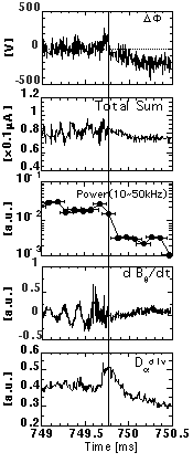
It has been claimed experimentally and theoretically that the radial electric field plays key roles for causing the L/H transition. So far the highly time-resolved and direct measurement of the potential has not been performed. The heavy ion beam probe is particularly suited for fast and the local measurement of the plasma potential. In order to study the physics of L/H transition, we installed a 500 keV heavy ion beam probe on the JFT-2M under collaboration program between NIFS and JAERI. The local plasma potential can be obtained by the measurement of the change of the secondary beam energy generated at the sample volume. Figure II.1.1-1 shows the rapid change of the potential at L/H transition triggered by a sawtooth. The potential changes positively by the sawtooth heat pulse in coincidence with the fast Da rise. After that, it shows that a very rapid drop (~100 V / 10 msec) of the potential together with a drop of the fluctuation in the secondary beam intensity and the magnetic field of dBq/dt. They seem to occur simultaneously. The potential goes down further to about -300 V with its time constant of a few hundred micro-second together with the fall of Da. We can not conclude the causality clearly, but the results suggest an important role of the change of the potential at L/H transition.

References
[1.1-1] Hamada Y., Ido T., Kamiya K., et al., "Fast Potential Changes at H-mode Transition in the JFT-2M Tokamak", to be published in Proc. of 17th IAEA. Conf. on Fusion Energy (Yokohama, 1998), postdeadline paper.
Figure II.1.1-1. Fast time behaviors at the L/H transition. The plasma potential(DF), the secondary beam intensity (Total Sum), the power of the fluctuation in the beam intensity integrated from 10 to 50kHz when the sample volume is placed around the separatrix, the magnetic probe signal of dBq/dt and Da intensity.
1.2 Electron Cyclotron Current Drive and Disruption Control
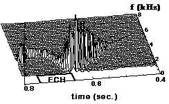
The effect of the Electron Cyclotron Heating (ECH) or EC Current Drive (ECCD) on the m/n=2/1 tearing mode [1.2-1] was investigated using the co-injection and the counter-injection of the electron cyclotron waves by using the new variable k// antenna [1.2-2]. The tearing mode is the cause of the mode lock disruption. The injection angle of the rf beam (f=59.8 GHz, fundamental O-mode, 170 kW, 0.1 s) was varied toroidally shot by shot from -25 to +25ー from the perpendicular direction to see the effect of the co-drive or the counter drive for suppression of the tearing mode with a single null divertor configuration of the JFT-2M tokamak. Experiments always showed a larger loop voltage drop in the co-drive case than in the counter drive case (both for the clock-wise direction and the counter-clock-wise direction of the plasma current). The estimated driven current was ~6 kA (ne=1x10¹⁹ m-3) in the center resonance condition (BT=2.15 T, IP=0.14 MA). We investigated the ECCD (at the island center) effect on the tearing mode (BT =1.82 T, IP=0.23 MA) and found that even the counter drive suppresses the tearing mode as well as the co-drive. The mode amplitude decreased to 1/2, and the mode frequency increased from 1.2 kHz to 3.5 kHz due to the decrease of the island width as shown in Fig. II.1.2-1. No drive case (perpendicular injection) brought the same result. These facts indicate that the present effective suppression is mainly brought about by heating and not by ECCD [1.2-2].
 |
| Fig.II.1.2-1 Magnetic power spectrum of the m=2 mode, BT=1.82 T, Injection angle=25ー, Counter-drive case. |
References
[1.2-1] Hoshino K., et al., Phys. Rev. Lett. 69, 2208 (1992); Hoshino K., et al., AIP Conf. Proc. 289, Radio Frequency Power in Plasmas (1993, Boston), 149 (1994).
[1.2-2] Hoshino K., Takahashi K., Bull. Ame. Phys. Soc. 43, 1932 (1998).
2. Peripheral Plasma Research
2.1 Compatibility of Dense and Cold Divertor Plasma with Improved Confinement [2.1-1]
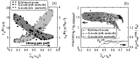
A study of the closed divertor has been carried out in JFT-2M with the aim of making a dense and cold divertor, compatible with high core confinement. Introducing a gas-puff into the divertor chamber, the baffling effect of the closed configuration is revealed by enhanced radiation loss localization and high neutral pressure in the divertor region, lower core fueling and the sustainment of energy confinement quality. The baffling effect is also enhanced significantly with the ExB flow and/or the current in the SOL by applying divertor biasing. A dense and cold divertor plasma up to  div~4x10¹⁹ m-3 and Tediv~4 eV together with the improved confinement modes up to
  /neG~0.7 can be brought by a strong gas-puffing as shown in Fig.II.2.1-1(a) and (b). The strong gas-puffing to an ELM free H-mode plasma led to the second transition to improved L-mode (IL-mode). H-factors of the ELM free H-mode and the IL-mode (without sawtooth) only degrade at their highest densities corresponding to an abrupt increase in the radiation loss over the critical value of Rpcrit~0.7 in the main plasma, which was caused by impurity accumulation. However, the IL-mode (with sawtooth) keeps a low radiation loss below Rpcrit and has favorable features for realizing steady-state high performance at high density. The UEDA-code simulations also show that the baffle plates produce a strong neutral buildup and the dense and cold state in the divertor chamber.
 |
| Fig.II.2.1-1 (a) Progress of the dense and cold divertor and (b) characteristics of the main plasma confinement in the ELM free H-mode, IL-mode (with sawtooth) and IL-mode (w/o sawtooth), when the main plasma density normalized by the Greenwald density limit neG is increased by gas-puffing in the closed divertor chamber. Variation of Rp (ratio of Pradtotal to input power Pin) in a discharge which reaches the highest density of each mode is also shown as a function of ne/neG in (b). |
Reference
[2.1-1] Kawashima H., Sengoku S., Ogawa T., et al., "Study of a Closed Divertor with Strong Gas puffing on JFT-2M", to be published in Proc. of 17th IAEA. Conf. on Fusion Energy (Yokohama, 1998), paper IAEA-F1-CN-69/EX3/4.
2.2 Compact Toroid Injection [2.2-1]
A dense and fast compact toroid (CT) injection is expected to be a core fueling method for a fusion reactor. The CT injection experiments in NBI heated plasmas including H-mode have been carried out in the JFT-2M tokamak. It was demonstrated for the first time that the CT penetrates into the core region of the H-mode plasma heated by 1.2 MW NBI with a rapid increase in the electron density at BT =0.8 T. Asymmetric radial profile of the soft X-ray emission indicates the CT penetration into the core plasma, while partial penetration in the peripheral region was observed at BT=1.3T. Incremental fractions of the soft X-ray intensity of the central chord and increasing rates of the line averaged electron density due to the CT injection becomes larger with deeper penetration of CTs. We observed the largest increase of the line-averaged electron density of ~0.8×10¹⁹ m-3 at a rate of 1.2×10²² m-3/s with the CT injection in an ohmic discharge at BT =0.8 T so far.
Reference
[2.2-1] Ogawa T., Fukumoto N., Nagata M., et al., "Compact Toroid Injection Experiment in JFT-2M", to be published in Proc. of 17th IAEA. Conf. on Fusion Energy (Yokohama, 1998), paper IAEA-F1-CN-69/EX1/16.
3. Advanced Material Tokamak Experiment (AMTEX) Program
3.1 Preparation for Ripple Reduction Testing with Ferritic Inserts
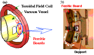
The negative magnetic shear configuration provides a prospect toward the steady-state tokamak operation. However, negative shear experiments in JT-60U showed an enhanced loss of ripple trapped fast ions [3.1-1]. Therefore, it is one of the most important issues to reduce the loss of fast ions for the steady state operation. In ITER, it is planned to use ferritic steel to reduce the toroidal field ripple (to reduce fast ion losses) [3.1-2]. In JFT-2M, ferritic boards (FB) were inserted between the present vacuum vessel (VV) and the toroidal field coils (TFCs) for the first time in the world in order to test reduction of the toroidal field ripple and the fast ion ripple losses. In order to reduce the fast ion losses, the ripple amplitude and its toroidal mode number have to be reduced [3.1-3, 3.1-4]. The guideline of the design to reduce the fundamental and the higher toroidal mode in the case of ferritic steel insertion is as follows: wider and thicker ferritic board should be positioned far from plasma, but inside the TFCs. A conceptual drawing of the ferritic board insertion on JFT-2M and a photograph of one of the ferritic board set is shown in Fig.II.3.1-1. Since its effect is not linear, its optimized thickness depends on the magnetic field. It is designed to consist of elements of 8mm thickness so that its total thickness can be changed by adjusting the number of elements. Measurements of fast ion losses without FB insertion were carried out before installation of FBs. Increments of wall temperature due to the ripple ion losses were observed between the TFCs by an infrared camera during tangential NBI heating. Both ripple trapped ion losses and banana drift loss ions were observed at the wall of the shoulder part and the mid plane part, respectively.
 |
| Fig.II.3.1-1 (a) Conceptual drawing of the ferritic board insertion on JFT-2M, (b) Photograph of one of the ferritic board set. |
References
[3.1-1] Tobita K., et. al., Proc.16th Int. Conf. on Fusion Energy, (Montreal, 1996) Vol. I, 497 (1997).
[3.1-2] Ioki K., et al., J. Nucl. Matter. 258-263, 74 (1998).
[3.1-3] Sato M., Miura Y., Kimura H., et al., Proc. of 20th SOFT, (Marseille,1998) 545 (1998).
3.2 Design of Ferritic Vacuum Vessel [3.2-1]
The ferritic steel is proposed for the structural material of blankets in SSTR and the advanced SSTR (A-SSTR). However, the error fields due to the ferromagnetism of the ferritic steel may affect the stability and confinement of high performance plasma. To clarify these issues, the present VV will be replaced with a ferritic VV in the second phase of AMTEX and compatibility between plasma performance and ferritic steel will be tested. Design study on the ferritic VV (20 mm in thickness) was carried out and following results were obtained; (i) For the plasma equilibrium, effects of a ferritic VV are small because the ferritic steel saturates easily by the toroidal magnetic field and its relative magnetic permeability is around two. (ii) Mechanical analyses of the ferritic VV indicate that the maximum induced stress (60 MPa) with the electromagnetic force due to the disruption is much smaller than the critical stress (325 MPa).
Reference
[3.2-1] Sato M., Miura Y., Kimura H., et al., J Plasma & Fusion Research, 75, 741 (1999).
4. Operation and Maintenance
4.1 Tokamak Machine
A drop of ground insulation resistance of the vacuum vessel at temperatures around 80ーC had been always observed during the baking of the vacuum vessel. The cause of the insulation deterioration was thoroughly inspected during the vent for the installation of diagnostic instruments in March 1999. Contact of a thermocouple wire and a cable connector of the gas-puffing system with a structure electrically connected to the ground was found, and contact between a lead wire of the baking heater and a structure electrically connected to the ground was also detected. These failures were completely fixed.
In the compact toroid (CT) injection system, a transformer was installed to reduce the noise in the low-voltage power supply and the baking system was improved. A CO2-based fire extinguisher was newly introduced for safety. A new electrode was also introduced to improve the performance of the CT system.
An infrared TV temperature measurement system was also installed for the detecting the ripple loss of fast ions before and after the installation of the ferritic board on JFT-2M.
4.2 Neutral Beam Injection System and Radio-Frequency Heating System
The neutral beam injection (NBI) system and the electron cyclotron resonance heating (ECH) system were operated fairly smoothly and were fully utilized for the experiments. In the annual maintenance of the NBI system, the residual-gas monitoring system was serviced. The renewal was also made of the optical transmitters in the retarding power supply, the storage batteries for the control system and the water pumps in the cooling system. In the ECH system, an intensive aging was carried out to prolong the injection time after the annual maintenance of the system including the transmission system.
4.3 Power Supply System
In the operation for the magnetic field measurement before and after the installation of the ferritic steel boards (in January and March 1999), the motor generators (MGs) #2 and #1 for the toroidal field coils were halted due to the flashover of the commutator, respectively. The flashover of MG #2 occurred due to copper drags of the commutator and that of MG #1 was caused by dusts stuck on the commutator. To overcome these problems, at first, the material of the carbon brushes was changed from greasy fumes to coke, and resistance to arcs and the contact of brush were improved. Filters will be installed in the air inlet of each motor generator to reduce the dusts.

