Objectives
To measure safety factor (q) profiles (current density profiles).
Principle
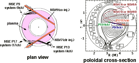
Dα or Hα line from a neutral beam (NB) in a plasma is split and polarized due to the motional Stark effect (MSE). The direction of magnetic field, from which the q profile is reconstructed, is obtained with the measurement of the polarization angle.
Diagnostic Method
The polarization angle of s component of Dα or Hα line from the tangential heating neutral beams, called #7B and #9B, is measured by polarimeters.
The polarimeter consist of mirrors, lenses, a pair of PEMs (photoelastic modulators) and a linear polarizer.
The light is transmitted to detectors in a diagnostics room through fiber-optic bundle cables of 120 m length.
The detector consists of lenses, an interference filter and a photomultiplier.
The output of photomultiplier is split into a 2 kHz low-pass filter and two lock-in amplifiers at the two reference frequencies from the PEMs.
The polarization angles are obtained from the output of lock-in amplifiers.
Specification
| Number of channels | : | 30 (17 for the P17 system, 4 for the P13 system, 9 for the P3 system) |
| Spatial resolution | : | 6-8 cm for the P17 system, 15-20 cm for the P13 system, 9-11cm for the P3 system |
| Time resolution | : | 10 ms |
| PEM | : | aperture size of 10 cm, frequencies of 20 and 23 kHz |
| Optical fibers | : | core diameter of 0.4 mm, about 20 fibers per each channel. |
| Interference filter | : | 0.3 nm FWHM, with a temperature controller to adjust the wavelength. |
| Photomultiplier | : | Hamamatsu R943-02 or R943-03 with GaAs photocathode |
Acknowledgments
Valuable discussions with PPPL and GA are gratefully acknowledged.

References
[1] T. Fujita, H. Kubo et al., Fusion Engineering and Design, 34-35 (1997) 289-292.
[2] T. Suzuki and T. Sugie, J. Plasma Fusion Res. 78 (2002) 411-416.

